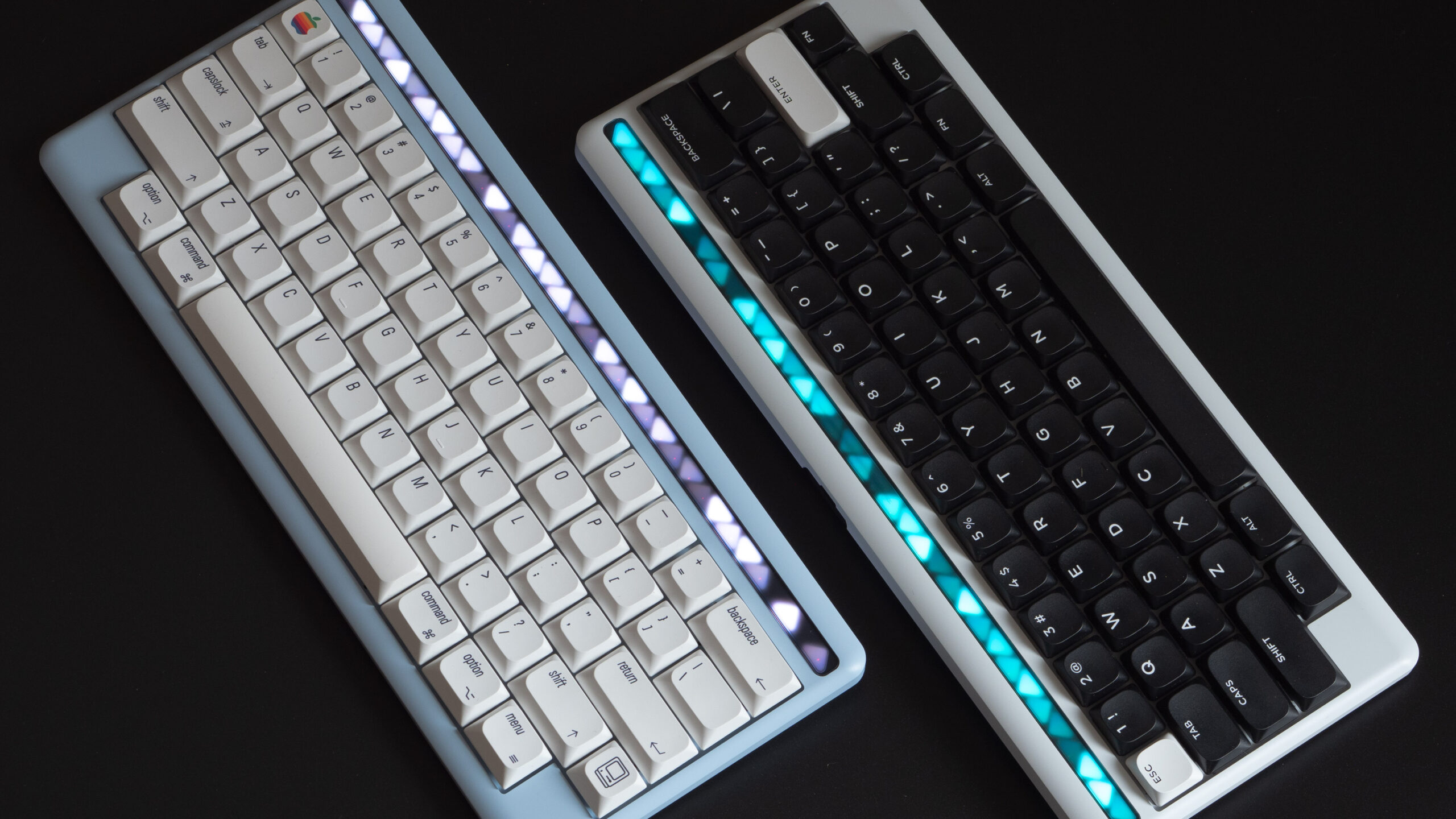
As I already mentioned in my first post – the LED strip diffuser needed a little bit more refinement. I recently got the updated parts in the mailbox, so I figured it’s be an excellent opportunity to document the teardown of one of the prototypes and give you a peek inside. Let’s get this thing opened up.

To start, we need to flip the keyboard upside down to reveal 8 external mounting screws. These are all countersunk M2.5 screws, that will be color matched to the metal accent piece in the bottom case. Once unscrewed, we can open the case. Some care is needed with disconnecting the battery lead. The connector clicks in from the top, so you need to either pry it up or gently pull at the lead. Take care with this, damage to the PCB is very unlikely but yanking too hard can still negatively affect the connector performance.

The battery is glued to the bottom using a stretch adhesive strip – meaning there’s a tab that you can gently pull on to remove it. While I wouldn’t recommend it unless you absolutely have to have to, I did my best so it’s not unnecessarily difficult.
In the other half, you can now clearly see the PCB and the daughterboard on top of it. They are held in place by four M2 screws – two each. The PCB screws use the same driver size as the rest of the case, but notice that the daughterboard screws are different. This is due to very tight space requirements in that part of the case so the same screws wouldn’t fit. I’m still actively researching the options in this area – ideally you’d be able to work on all the screws using the same driver, but just be aware that this is something that could still change. Once unscrewed, the daughterboard and PCB will come right out. If you’re leaving the switches in like I did here – it’s easier to remove them from the other side – you’ll want to gently pry on the PCB to loosen the hot-swap sockets so it comes out.

With the PCB removed, we now get a clear look at the inside of the case. There’s two pieces of foam sandwiched between the case and PCB. The narrower one – positioned towards the top, under the LED strip – prevents the light from leaking to other ‘cells’ in the strip. It is critical for the display to work as intended. The larger piece however, it’s there to help improve the board’s acoustic performance but also is completely optional. Specifically, it helps get rid of any pinging noise, which can otherwise be quite prevalent depending on the switches used given the construction of the chassis. I’d personally recommend leaving it in – buy you’re free to experiment as much as you wish :).

The machining on the upper case itself is also worth a quick mention. Minimal and evenly spread contact points between the halves eliminate any rocking/pinging that could otherwise creep in due to surface imperfections or material fatigue. The plate is also ~40% thicker than usual low-profile keyboards, at 1.7mm thick. This makes for a solid and even feel across the entire surface. The switch sockets are still machined down to 1.2mm for switches to clip in correctly and to not obstruct the stabilizers.
Last but not least, the triangular display pattern is integral to the case itself. I believe it’s the only right thing to do – it’s a core feature of the whole design while it also shows off the level of craftsmanship that went into it. Executing such pattern to a high degree is no trivial task.

Back on top of the case, the display assembly is glued to the rest of the case. The adhesive isn’t overly strong – everything is held in place quite firmly, but will come loose with enough pressure applied from below. It does take slightly more than a light tap, but it’s extremely convenient for working with the prototypes without having to resort to heat guns. The old combo comes out, and a fresh updated pair goes in.
Unfortunately, the new diffuser samples I got are not quite up to spec, causing some fitment issues as the assembly is now slightly too thick. This has to do with how they were cut and luckily, it won’t affect production parts for which a proper die will be made. For now, it means the lights look slightly less sharp than they actually should because of the layers not perfectly adhering to each other. Let’s look at some before and after shots:


Besides the fit issues described above, I’m very pleased with the updated material and will be moving forward with it. The light is spread much more evenly in each cell which makes their triangular shape stand out even more. Additionally, you can now clearly distinguish different shades of the same color. This is especially noticeable when you look at the background behind the rainbow effect. You’d be hard pressed to guess there’s a gradient to it in the old version (black keyboard) compared to the new one (blue) where it’s impossible to miss.
On a side note, that’s also why per-key RGB ends up so underwhelming in a lot of the keyboards. Unless specific switch and keycap materials are chosen to bounce the light in a pleasing way, you end up with the common Christmas tree aesthetic. Even then it’s not a given it’ll work due to the geometries and spacing involved. Anyway, I digress…
Let me know your thoughts on the update! And consider joining us on Discord if you with to take an active part in the design process.


Leave a Reply